Indie Game Devlog 05 - Materials and Shaders
Last time, I was deriving a pipeline for face animations. In the process I was making an implicit decision about how much time I’ll be committing to this part of the game versus what sort of impact and clarity into the characters it will provide for my audience.
Materials are similar.
I know I have neither the talent nor the time to commit to hand painting textures for my environments, hundreds of assets, and perhaps dozens of characters. But I also know flat colors on low poly models isn’t going to be visually interesting enough. What’s in the middle of these two extremes?
The possibilities space is too large
The constraints of “looks good” but “doesn’t take forever to make” still don’t give me a lot of direction. I guess that’s where my personal taste comes into play.
I’ve been enjoying all sorts of “hand-crafted” looks lately. Imitating certain real-world crafty materials in 3D feels like it doesn’t have the same sort of uncanny valley that hyper-realism does. Modeling clay, paper, felt, wool; these have all been used in stop-motion filmmaking since its early days. By picking one material it’ll theoretically be easier for me to keep to a theme, optimize performance, and optimize development time.
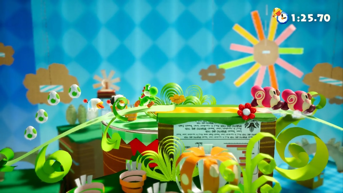
I felt one material and a constrained color palette was a good north star.
The goal: clay
I can’t really articulate why, but I think my game’s world realized in clay would be fun to see. It obviously works well with the stop-motion animation style I was experimenting with last post.
For learning and prototyping purposes, I decided to go with clay. But of course, this is all still prototyping.
Other potential materials might be paper or wool knit. The goal at this point is to understand whether any of these choices imposes additional technical constraints or pitfalls.
Untangling the complexities of materials
This is where my self-taught background starts to leak through again.
I’ve been mostly working inside the world of Blender and its shader editor during my 3D journey. Thus, it wasn’t clear to me whether I was learning fundamental properties of shaders or specific Blender quirks. I first confronted this while porting my Biki character from Blender to SceneKit, but due to the nature (limited timescale) of that project, I just did my best to get to the finish line without really tackling the problems I was facing head on.
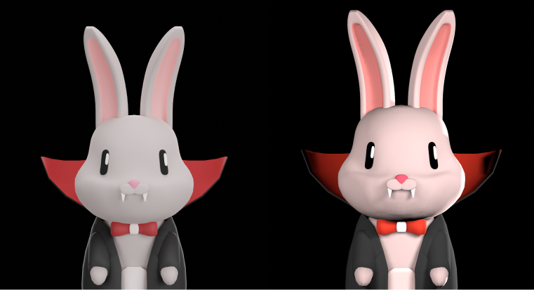
This week I’ve needed to rectify all those knowledge gaps.
Let’s start in Blender and try to work through all the complexities of materials.
Shaders
Shaders in Blender can be written in code, but more commonly they are described as nodes in a graph with the primary output “describing lighting interaction at the surface…, rather than the color of the surface,” quoting the Blender docs.
Shaders really only have meaning when applied by a rendering engine to a mesh. It’s common to see a preview of shaders on a spherical mesh under neutral lighting from an HDRI.
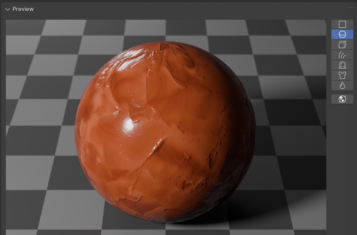
Blender has two built-in rendering engines: EEVEE (simple) and Cycles (complex). Each has its own supported feature set, which means shaders can produce similar results but are by no means “universal”. We’ll discuss this further when considering how our shaders import into Godot, which has its own rendering engines.
When you create a new material in Blender, by default it creates a principled BSDF node in the shader graph. For a beginner, the principled BSDF node has an overwhelming number of parameters, but the most commonly used are base color (diffuse), metallic, roughness, and normal.
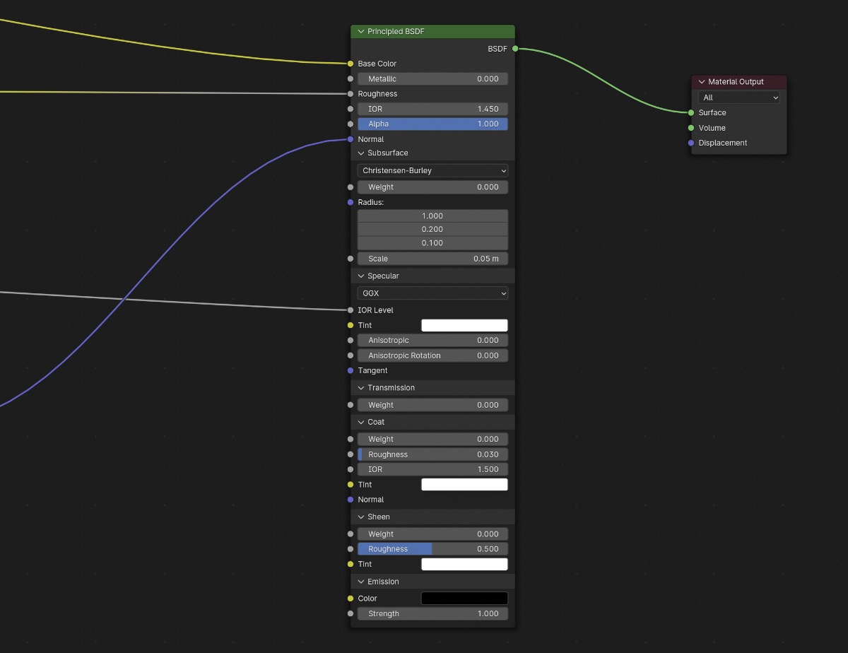
In theory, the principled BSDF base shader can describe the light bounce behavior of any photorealistic material.
Setting a few of these parameters to constants can get you in the ballpark of some interesting looks.
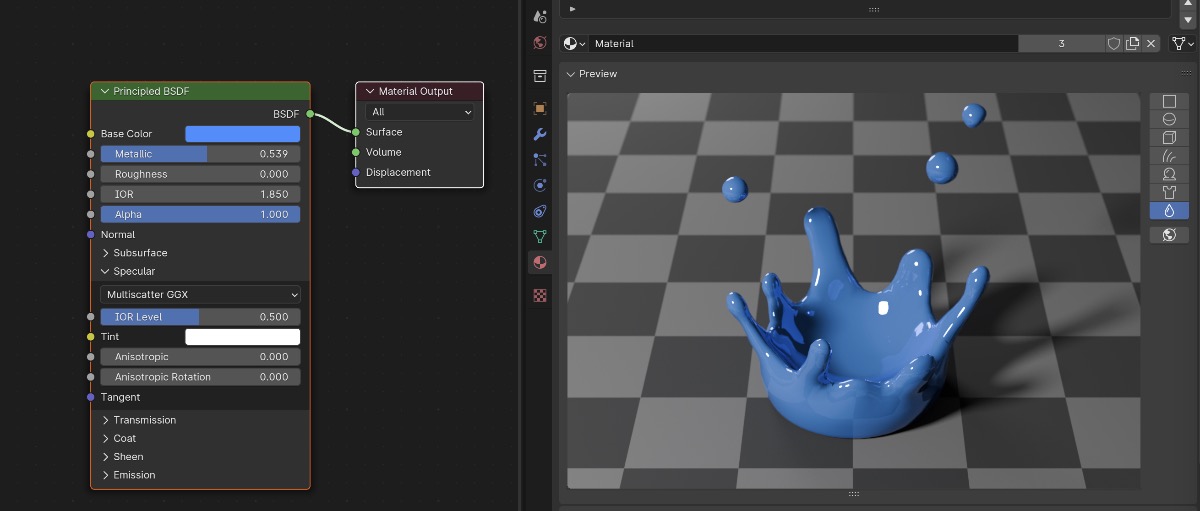
But most materials in real life do not have the exact same property values across their entire surface. For example, an orange has lots of tiny bumps all over it, and some parts are shinier than others. We need some way to vary the properties of the material.
Varying shader inputs
The shader program is run in parallel on the GPU for every point of the mesh it’s applied to. There are two options for controlling the mapping between each point and the value reported to the shader input.
- Texture and UV map - provide a 2D bitmap and specify how the flattened mesh maps onto it
- Procedural - provide a mathematical function that takes an input value and produces an output value
These two options are not mutually exclusive, and are very commonly mixed and matched across the shader graph.
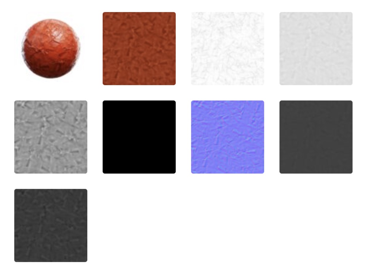
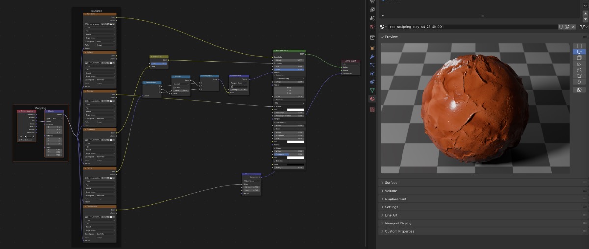

Texture is the most compatible while procedural is the most flexible. Textures trade off less computation for more memory, since the data for each pixel will be stored instead of calculated on the fly.
The compatibility of textures is reflected in websites hosting thousands of both free and paid textures in the form of groups of image files (for example, the above clay texture is from CGAxis). These files can mostly be plugged directly into any rendering engine that supports PBR shaders (like Blender’s principled BSDF) with similar rendered results.
Shaders in Godot
Godot has its own rendering engine and shader support. There are 4 ways to make shaders in Godot:
- Write shaders in Godot’s shader language, with many examples available on godotshaders.com, or converted from the more common GLSL shader language.
- Use a StandardMaterial3D, a PBR shader similar to Godot’s principled BSDF shader.
- Use visual shader language to create a custom shader, most similar to Blender’s shader nodes.
- Import the shaders from Blender, and they will be best-effort mapped into a StandardMaterial3D automatically.
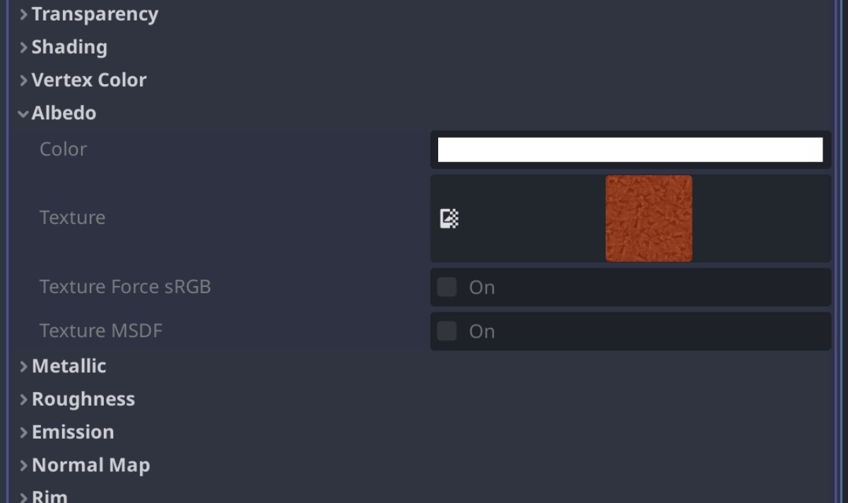
All shaders are eventually converted to the platform’s shader language. The other non-text options can often be automatically or manually mapped between one another, for example from StandardMaterial3D to a text shader.
Note that there actually several types of shaders: spatial (3D), canvas item (2D), particle, sky, and fog. In this post we’re primarily discussing spatial (3D).
Implementing a clay texture
With that background, let’s jump into the process of actually getting a clay material onto our character in Godot.
Goals slash success criteria
First off, there are myriad ways of implementing a clay-looking material so I’ll enumerate my goals.
- Prefer creating and configuring shaders in Blender over Godot - Blender not only has the most mature tools, but I’m most comfortable with them. There is less chance of upstream changes breaking the downstream source data.
- Make the shader look good, but not perfect - I’m still at the point where all parts of the project are in flux, so perfecting one vertical doesn’t make sense.
- Minimize manual conversion steps in the pipeline - I want to avoid needing to click a hundred buttons in a certain order after each small change to the source data. If I can reuse the existing automation, that’s best. If it’s possible to eventually write my own automation scripts, that’s second best.
- Ensure content creation is as easy as possible - Making content (e.g. characters, props, environments) is a manual process, so ensuring the artistic parts of modeling and coloring are straightforward is ideal.
- Keep performance and optimization in mind - I know very little about how to keep performance in the ballpark, but I want to be careful that intense rework at the end of the development process due to poor performance will not be required.
Options for the source material
There are a few options for getting the bulk of the clay shader in place.
- Buy a procedural shader - Clay Doh is a paid Blender shader graph that seems to be the industry standard for very customizable procedural clay material.
- Set up a custom procedural shader - There are number of tutorials on YouTube that walk through how to make a custom procedural shader, each of varying quality.
- Start from a texture - There are several clay shaders image texture packs that include diffuse, normal, roughness, etc. images that can be plugged directly into the principled BSDF node after the mesh is UV mapped.
Using raw textures (option 3)
I downloaded an overstylized clay texture and dragged in the material to my project. The node setup was relatively simple: UVs mapped to each type of image texture plugged into the corresponding inputs of the principled BSDF shader. As shown earlier, it seemed like there was some extra channel flipping for the normal map.

This looked somewhat okay at first pass in Godot.
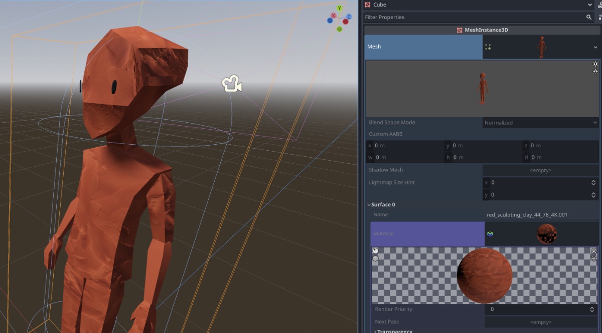
Spot checking the imported StandardMaterial3D, most of it was imported correctly. One big missing piece was the displacement map though.
Displacement
In shading, there are 2 ways to make meshes look deformed (not perfectly smooth): normal maps and displacement maps. They’re not mutually exclusive.
Normal maps tell the rendering engine which direction every point on the mesh is facing. The rendering engine then can “fake” depth that doesn’t exist on the mesh. In many cases, this sort of depth is convincing. Normal maps are always the first choice over displacement maps because they’re cheap to for the renderer to calculate and widely supported across renderers.
Displacement maps in contrast actually alter the positions of vertices on the mesh before the renderer performs shading. This results in more realistic shading, especially noticeable on the silhouette of the mesh (which the normal map has no control over). The displacement process can be costly though, and is not as well supported across renderers.
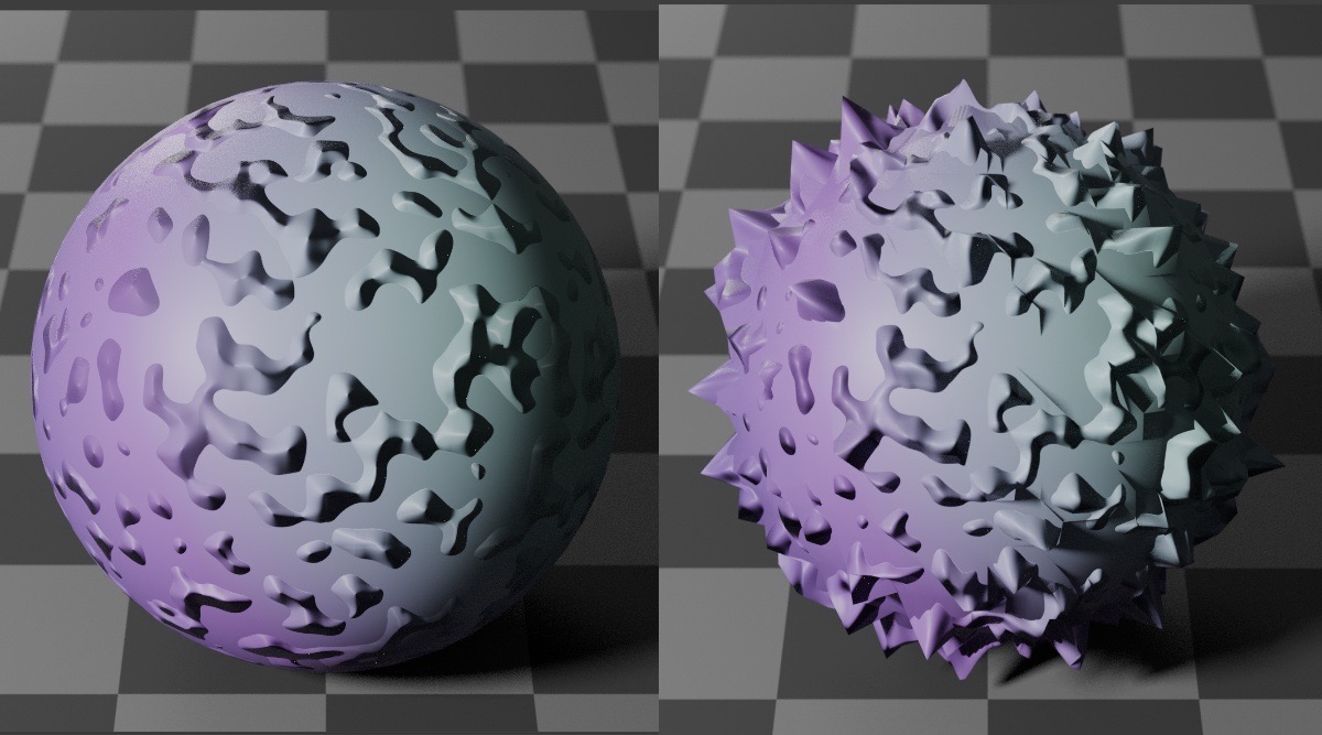
In order to displace vertices the vertices must exist on the mesh. That means low poly meshes with simple geometry must be subdivided to create enough vertices for the displacement map to be applied and have the intended effect. Normal maps don’t have this limitation: they can fake depth on a low poly mesh at the level of detail of the input texture or input function.
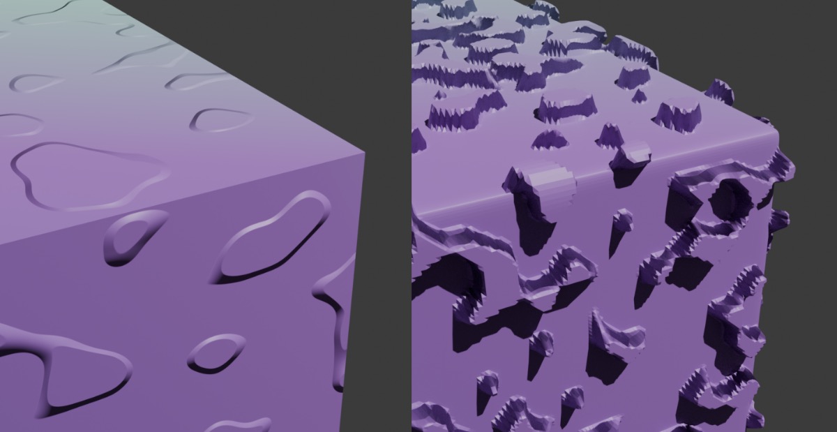
Godot’s build in shaders have no direct support for displacement maps at the shader level. A (relatively simple) custom spatial shader must be used. Blender’s EEVEE rendering engine also has no support for displacement maps at the shader level. Blender’s Cycles rendering engine however does have direct support for displacement at the shader level.
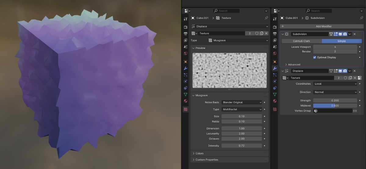
The workaround for implementing displacement before the shader is to use Blender’s displacement object modifier. The displacement modifier simply applies the displacement map to the mesh before handing the mesh off to the shader.
The result of raw textures
I applied a subdivision surface modifier (to create more vertices) and the displacement modifier to my character in Blender. I didn’t use the displacement texture supplied in the clay texture pack, instead using a generated noise texture to get a more modeling clay look.
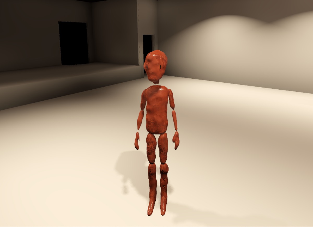
The subdivision surface modifier splitting the joints was an unintended side-effect, but it’s an interesting stylistic choice that’s also inconsequential implementation-wise, so I let it go.
This was looking alright! I was already itching to swap out the clay texture for a different one or otherwise tweak settings, but I prioritized solving the next big problem: diffuse color.
Investigating a flat color workflow
The clay shader came with its own diffuse texture. The detail of the texture matches that of the roughness, specular, etc. textures. The difference with those is that the diffuse texture’s primary color is a bold red.
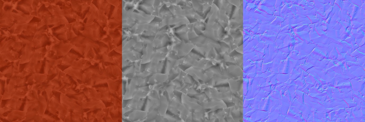
I certainly don’t want all my characters and environments to be the same color red, so I needed a way to give myself the flexibility to reuse this material across meshes and faces.
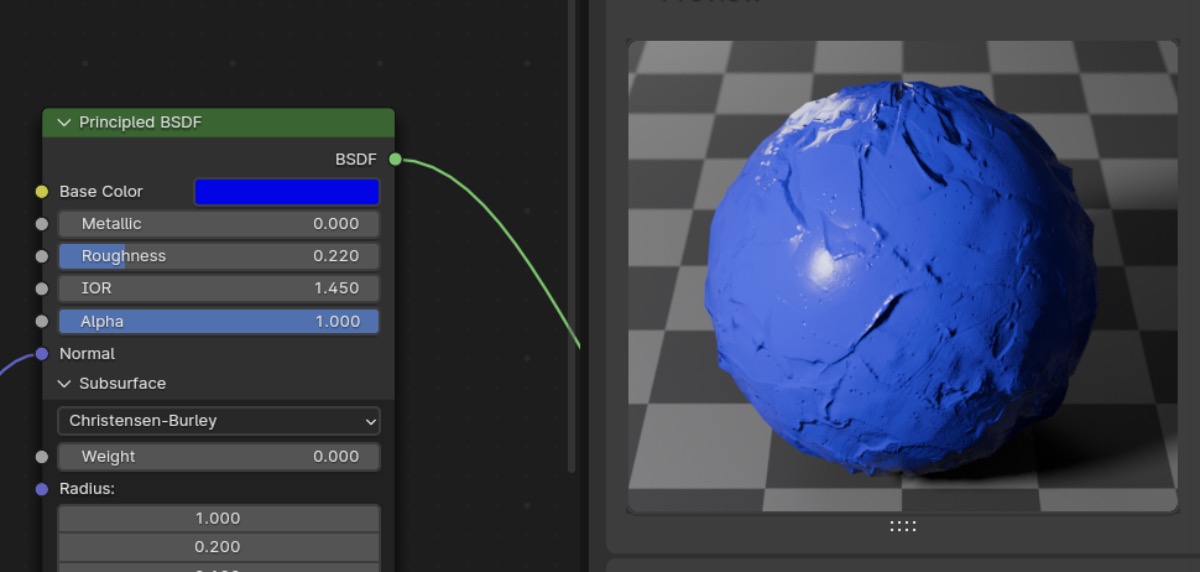
I started by adding a simple hue shift node between the diffuse texture and the base color input of the PBR texture to remap the color. For example, red to blue.

Although this works in Blender, in Godot the color ramp was ignored. This was another reminder that even the simplest of procedural operations would not work out of the box in Godot.
Then I tried disconnecting the diffuse texture and using a solid color. In my opinion, this looked good enough that I felt comfortable pursuing a diffuse color mapping solution that ignored the base material’s diffuse texture entirely. The normal map and other PBR components provided enough detail.
Assigning flat colors to vertices with UV maps and a palette texture
I now needed to tackle the second part of the problem: mapping individual vertices to separate base colors, perhaps on a fixed palette.
One of the more popular ways to map vertex colors to a flat color palette is to use UV maps.
- Associate a palette to a material as 2D bitmap texture.
- Create a UV map for each mesh.
- Scale and move vertices of the mesh around the UV map over top of the pallete.
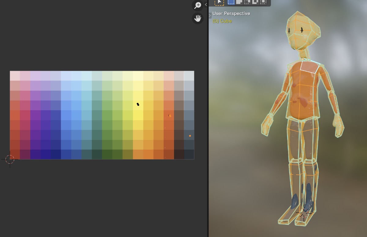
This workflow is relatively ergonomic to author. It allows flexibility within meshes when necessary but is also easy to use with meshes that are a single-color. There’s consistency by using a single palette. It’s performant since we can reuse the same material and texture across any number of meshes.
And it exports to Godot without any problems… well, as long as you only need one UV map.
Multiple UV maps
Why would I need multiple UV maps? The roughness, specular, normal map, etc. textures all require a more standard UV map; one that utilizes the full area of the texture.
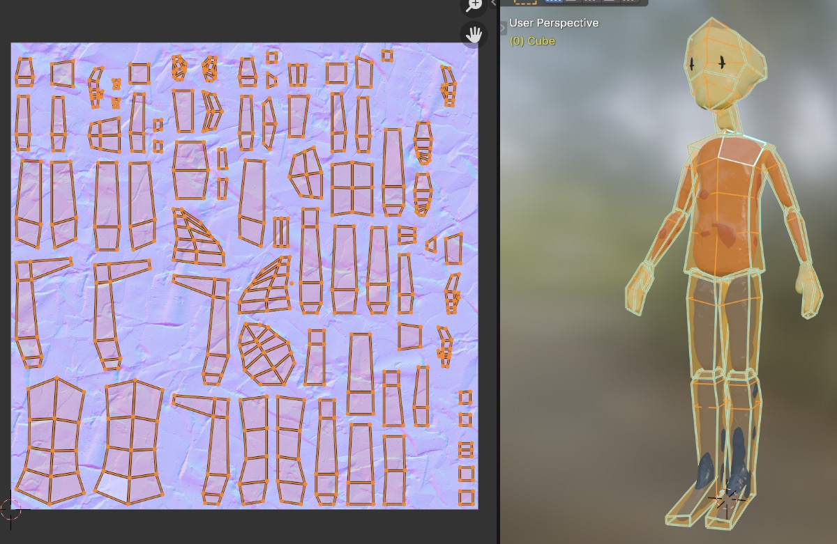
That meant I needed two UV maps: one for diffuse (base color) and one for the other non-diffuse PBR components.
Luckily, Blender can do multiple UV maps!

However, when I checked the result in Godot I found that my second UV map was ignored. Godot has support for a second UV map, but it seems like its purpose is for some sort of light map. I investigated for a while, but eventually gave up.
In parallel to this thread of investigation, I was also jumping back to explore the options for procedural shaders.
The problem with procedural shaders
With the earlier tests, including altering the base color texture with a hue/saturation/value node, I figured out that the automatic Blender-to-Godot import/export feature (via the GLFT format) does not handle procedural shaders well. It makes sense, after all the shader languages and visual node features are quite different.
There’s not much I can do to get around this limitation directly (e.g. somehow implement better support directly in the import/export pipeline).
I was nearly stumped at this part, but stumbled into a potential solution along the same lines as my previous solution to the animation modifier problem from last time: baking.
Texture baking
The solution to using procedural nodes in my shaders seemed obvious in retrospect once I started to internalize the relationship between the PBR base shader (aka principled BSDF shader in Blender) and its inputs.
The inputs to the PBR texture could always be converted to separate 2D bitmap textures as long as there was a UV map for each mesh to provide a frame of reference for the mapping.
That means I could perform a process called texture baking for each PBR texture input. Texture baking takes each input to the PBR texture and converts it to a flat 2D bitmap texture. Blender supports texture baking with its Cycles rendering engine. The process is somewhat manual and error prone, requiring the creation of 2D bitmaps, plugging and unplugging nodes, waiting for the render to complete, and more. But the process can be at least partially automated with a choice of Blender plugins.
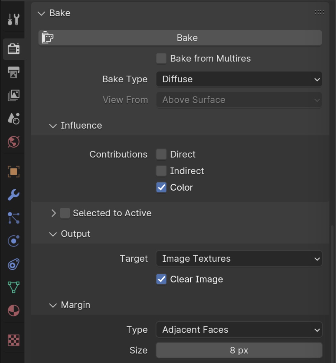
With texture baking, I had essentially found an escape hatch to ensure anything I dreamt up in Blender could be realized in Godot. Of course with some caveats I’ll discuss later.
Texture baking a base color texture map
Jumping back to my multiple UV maps problem, I realized I could solve this problem with texture baking.
- For each mesh:
- Create a second UV map targeting the color palette texture and set these in shader node graph.
- Run the texture baking process for just the base color/diffuse PBR input.
- Unplug the color pallete texture node graph from the PBR shader.
- Plug in the baked texture’s node into the PBR shader.
The baked texture matching the primary UV map looks like this:
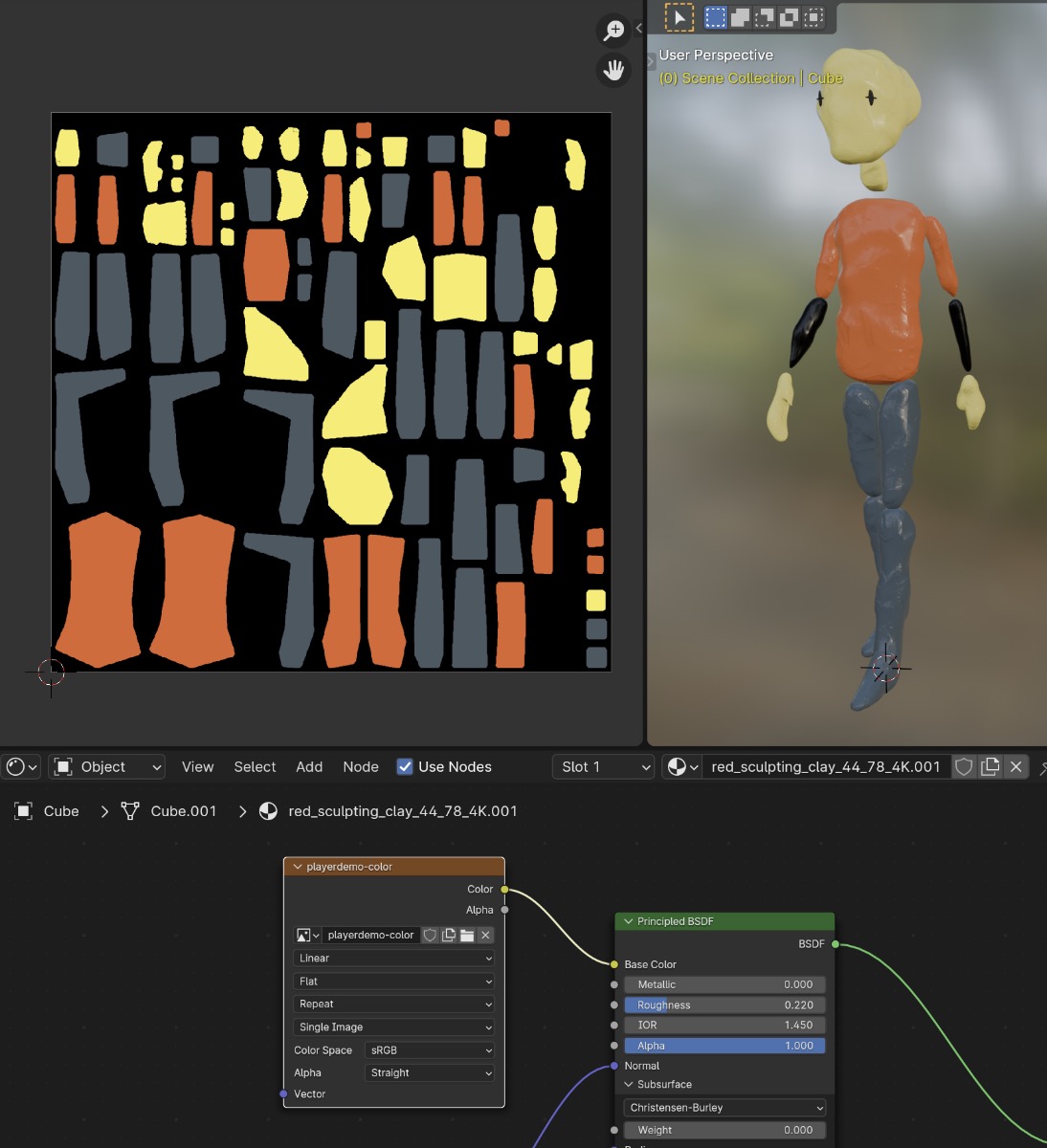
(Seems like I messed up the UV map for the lower arms.)
And importing it into Godot looks like this:
So baked textures work in Godot!
However, the downsides are that:
- The texture baking process is at least somewhat manual and tedious.
- The texture baking process must be re-run if the mesh or shader graph changes.
- One diffuse texture per mesh is required, at (presumably?) the same resolution as the other textures.
- The diffuse texture will end up with a lot of duplicate/wasted space.
It was great to have discovered the texture baking option. Not only because it allowed flexibility in color mapping, but also because it opened the door for using fully procedural shaders in Blender.
Generated texture space
UV maps aren’t the only way we can associate a texture to points on a mesh. If we look at Blender’s texture coordinate node, we can see that there are several options:
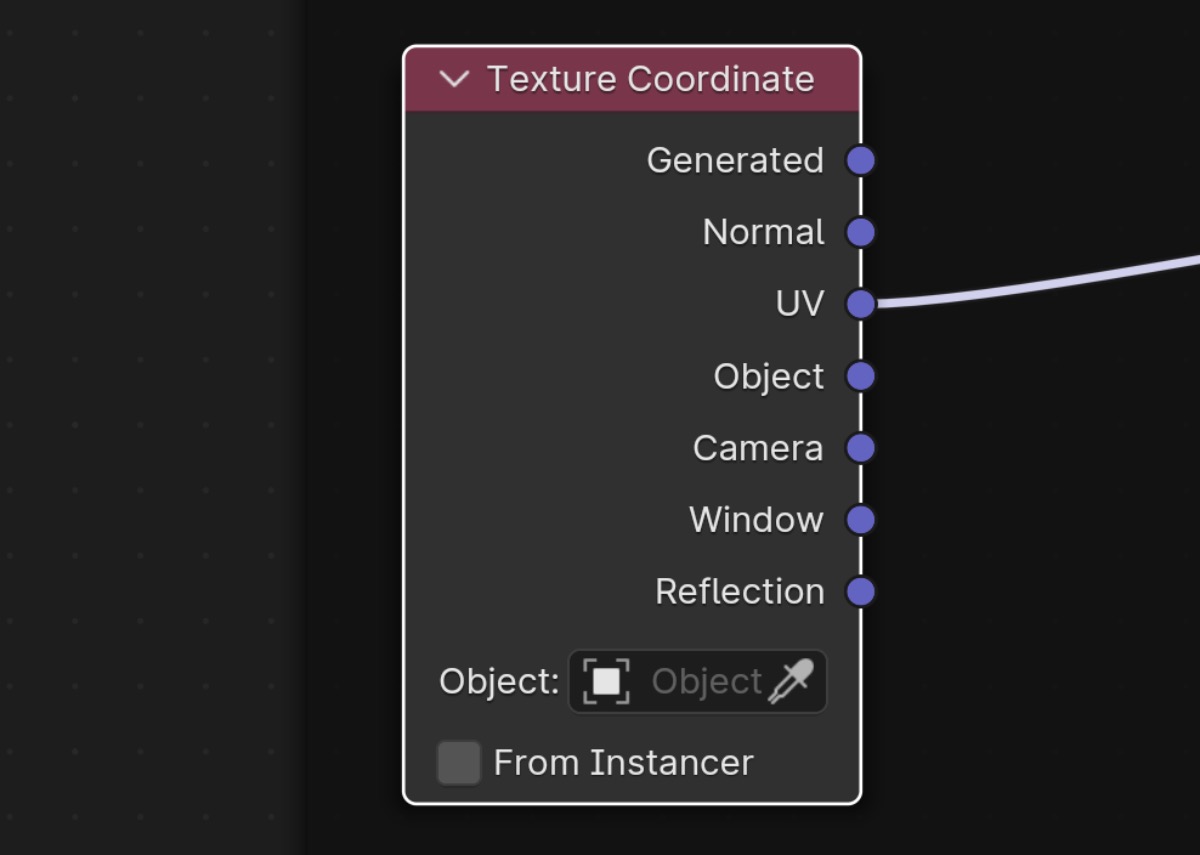
The Generated texture coordinate is something we can explore. Generated is controlled by another panel in the object data properties called Texture Space.
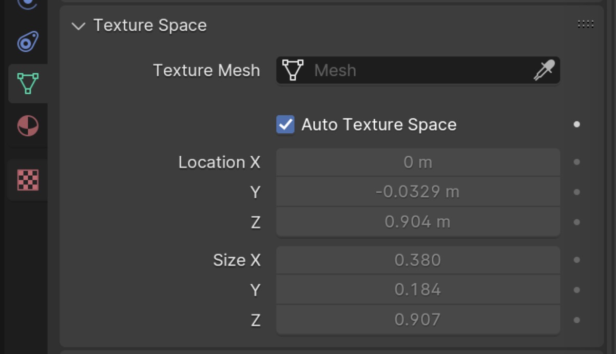
By default, the generated texture coordinate is created automatically by calculating a fitted rectangular bounding box around the object. We can view the bounding box by going to the object properties panel and checking Texture Space under Viewport Display.
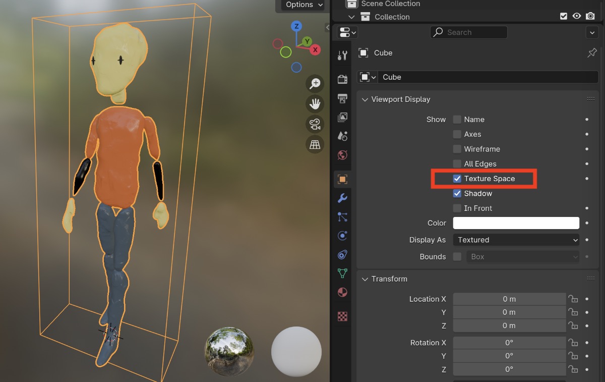
I’d never understood why sometimes my procedural textures looked weirdly stretched on one axis if applied to an obviously non-square mesh.
The way to fix this (besides manually creating a UV map), is to disable Auto Texture Space and change the size XYZ values to be equal.
In theory, using the generated texture coordinates for the non-diffuse parts of the clay material would free up the UV map to be used for the palette texture technique discussed earlier.
I tried setting this up in Blender and checking the results in Godot. Unfortunately, it seems like Godot will always use the UV map.
Another swing and a miss; generated texture coordinates couldn’t be a solution to my multiple UV map problem.
Texture painting
I’ll give an honorable mention to texture painting as an option for assigning colors to the diffuse input, even if I’m not planning on using it (I simply don’t need the level of detail it provides).
The most flexible option for assigning base colors is to create a blank texture and paint colors on it. The downside of course is that, like the texture baking option above, you’ll end up with one texture per mesh.
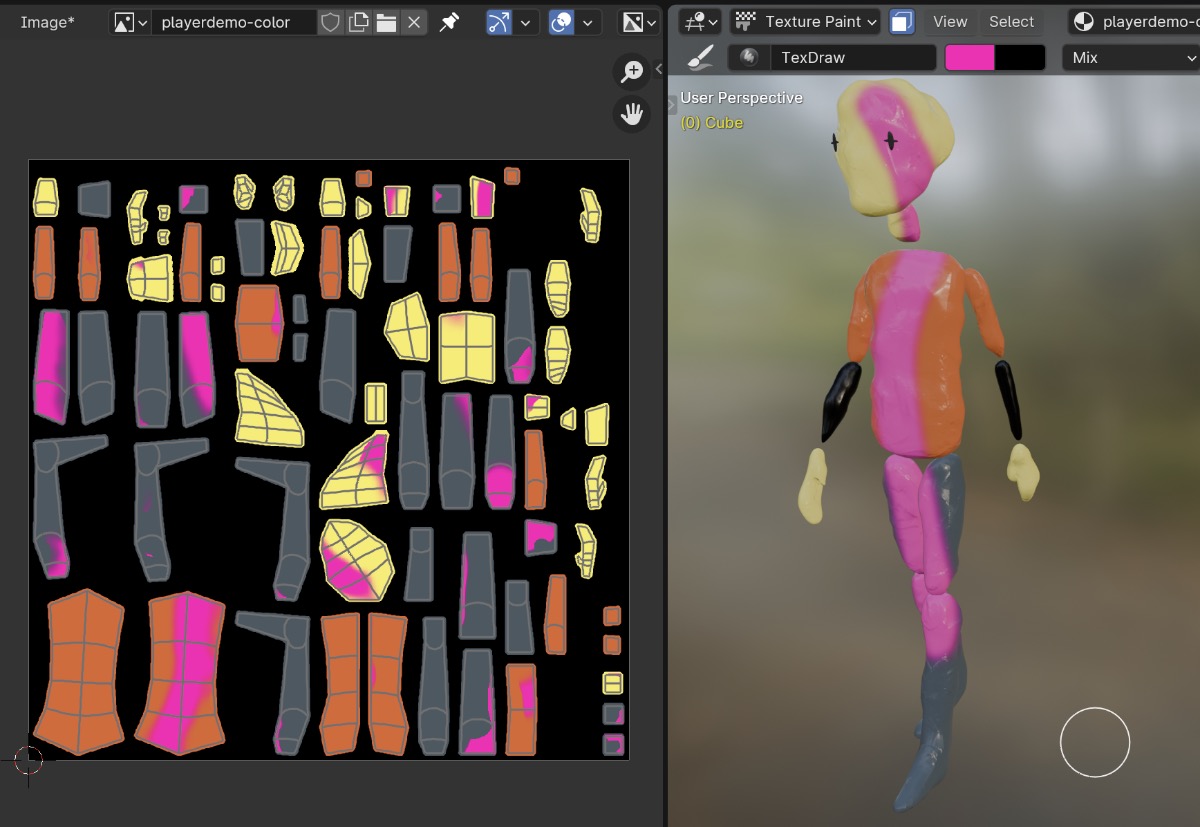
The upside is that this is a well-beaten workflow path that has lots of tooling support.
Using one material per base color
Another option for a flexible base color worflow I want to add to the list is using one material per base color.
An overview of this workflow:
- Create the material that will be used as a template.
- Separate out the material so it has a single color RGB input node.
- Optionally group all other nodes except the RGB input node into a node group.
- Duplicate the material for each required color.
- In Edit mode, select each face and assign the proper material to it until all faces are assigned.
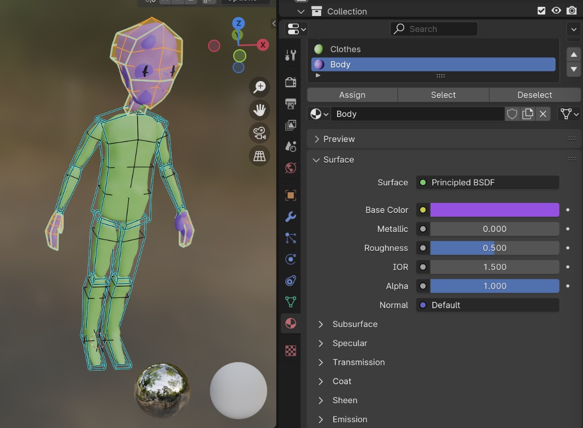
I’ve used this workflow regularly in the past. It’s relatively ergonomic for meshes whose base colors are limited and map closely to their faces. Or if you have the flexibility to modify the mesh to add vertices where you need color separation.
I’ll definitely have to use this workflow in the case that the characters or environment have a non-clay material. Perhaps something transparent or emissive (like a neon light). But in the general case, the one-material-per-color can become cumbersome to maintain when there are lots of colors in use across meshes and files.
The Godot importer handles this workflow without a problem.
Assigning base colors using color attributes and vertex paint mode
The last option I found for base colors is assigning colors via the Color Attributes and vertex paint mode in Blender.
Under the object data panel, there’s a section called Color Attributes. Creating a new entry here allows color data to be associated with individual vertices on the mesh.
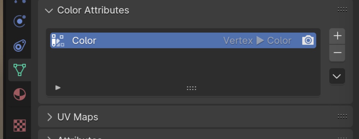
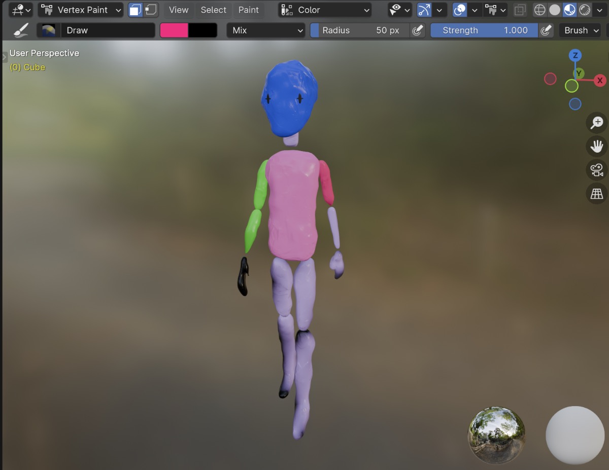
Switching to Vertex Paint mode in the viewport allows us to paint colors on directly on the vertices of the mesh using a few basic painting tools.
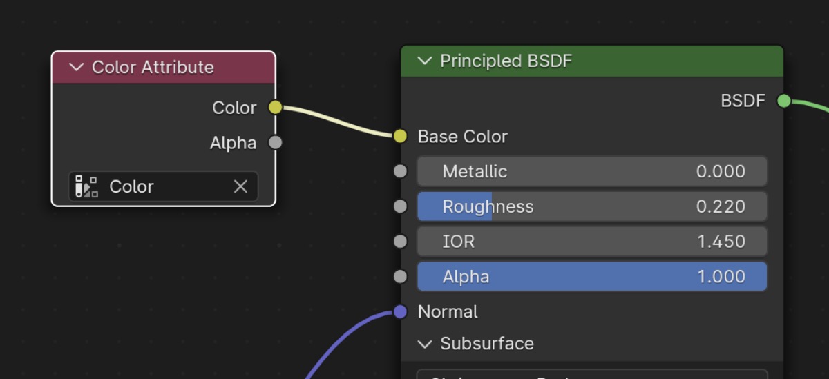
Then in the shader, we add a Color Attributes node and plug it directly into the base color input of the principled BSDF node.
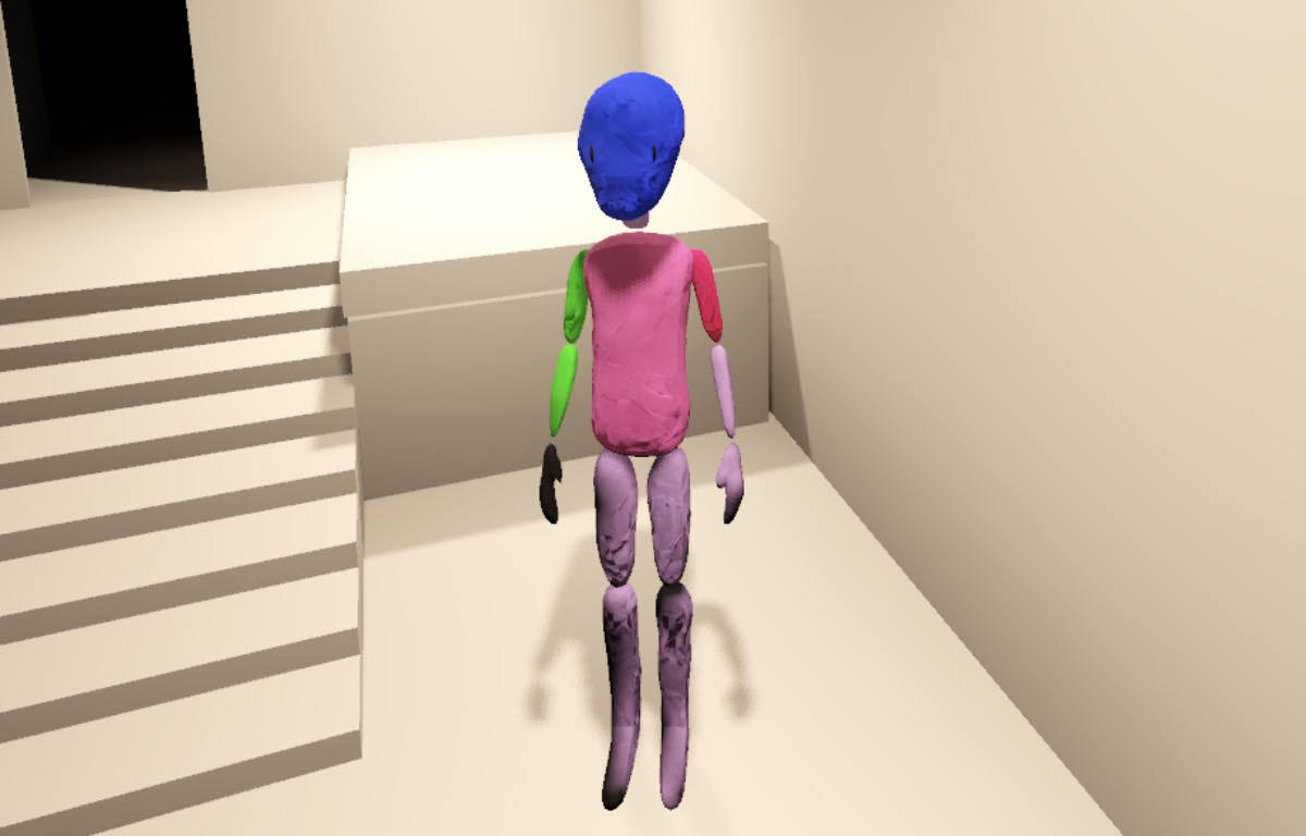
I was very much not expecting this to import into Godot. But I gave it a shot anyway and… wow, it worked!
I found the actual process of using vertex paint mode a bit clunky. Generally, I feel like I want to paint faces rather than vertices, but that workflow is much less streamlined than rotating around the model and painting the individual vertices.
Summarizing the options
OK, so that’s a lot of options to consider. It’s still tough to weigh the pros and cons of each without doing a dry run of modeling, texturing, and exporting a handful of character and environment models.
I may be able to get away with finding a decent clay texture pack, using that directly for the non-diffuse PBR inputs, then committing to a vertex painting workflow for the diffuse input.
However, I’m still considering buying the Clay Doh procedural shader because it looks really nice. Going the full procedural route would require experimenting with a texture baking workflow and then UV mapping all my objects in reference to the baked textures.
For now, I feel good about having explored the problem and solution space well enough to be able to implement a pipeline that makes realistic aesthetic compromises a bit further down the line.
And I’m sure there’s at least something I’ve missed in the Blender/Godot importer that could make any of the above options more streamlined.
What’s next?
I think diving deep into character design is the next important step. Character design is probably something I should have spent the last few years studying and practicing before getting to this point but… we’ll see what I can pull off!
Until next time.